 |
 |
The chapter is organised into three parts: 1) a discussion on VRML, 2) an introduction to the system architecture and 3) problems for dynamic creation of VRML worlds. VRML is a carrier of the scene parameters needed for the visualisation and interaction and therefore the chapter provides a detailed review. VRML syntax is discussed to specify whether some of the parameters (and which) have to be stored in the database. The software for creating VRML worlds, and their suitability of urban data is discussed in order to select the most appropriate way for automatic building of VRML worlds. The visualisation software (i.e. VR browsers) is investigated to detect to what degree the principles of VRML specifications are implemented and what are the problems. The issue is related to the correct visualisation.
An approach to retrieve and update 3D spatial and non-spatial data over the Web is introduced. The basic operations (i.e. select object, query and manipulate) needed by the users are then discussed in detail to exhibit the feasibility of the suggested approach. An extended commentary on essential factors related to the dynamic creation of complex VRML worlds (i.e. ensuring means for composition of queries and display of spatial results) aims to clarify whether some parameters require permanent storage in the GIS model.
Specific visualisation requirements derived from the VRML
syntax, visualisation software and the client/server architecture are formulated
at the end.
4.1.1 Visualisation of urban models in VRML4.2 System architecture for a Web 3D GIS
4.1.2 Approaches to design VRML worlds
4.2.1 Query, visualisation, modification4.3 Visualisation requirements
4.2.2 Creation of VRML documents on the fly
The VRML syntax is based on structuring units called nodes, which consist of: 1) the node-type (i.e. name), 2) parameters (fields), which characterise the functions of the node, 3) special fields for input and output events (eventIns, eventOuts), which control dynamics in the scene and 4) the body of the node, which contains particular values or other nodes. More than 50 standard nodes provide means to define scene and dynamics.
Several nodes are devoted to the design of the scene(see Chapter 2), i.e. description of geometry (regular and irregular shapes), illumination (directional, spot, point and ambient lights), materials and textures (draping and mapping of JPEG, GIF, PNG image file formats). The node dealing with geometry, colours and textures, i.e. the shape node, has three basic sections: appearance, geometry and dynamics. Theappearance node cares about the "solid" perception of the shapes, i.e. material (diffuse and specular colours) and texture. Since the concept of simple illumination and shading models is adopted, most of the browsers provide only Gouraund and Phong shading. "Attaching" texture to surface of the objects is supported in two ways: 1) simply wrapping a surface with an image, and 2) texture mapping. The texture mapping requires a second node to be specified, which contains the image co-ordinates, corresponding to the co-ordinates of the geometry. The geometry of 3D objects can be described by using predefined primitives (cone, box, sphere, etc.) or by sets of faces, which are represented by co-ordinates of points. The node maintaining faces, which is important for the thesis (see below), is presented by two sections: 1) co-ordinate section, which contains all the point's co-ordinates composing an object and 2) description section, which holds an ordered lists of points constituting faces that border objects (see Figure 4-3). The normal vector of each face is computed on the basis of the right-hand rule. For example, the normal vector of a wall with anti-clockwise orientation of the points has a direction toward outside the building.
Combinations of other nodes, i.e. sensors, routes and interpolators, introduce dynamics. Sensors detect either viewer actions (e.g. mouse move, click, drag), or time changes, or viewer position (visibility, proximity, collision). Routes direct the captured event to interpolators to alter some fields (colour, position, orientation and scale). This mechanism provides mostly direct animation, which is often insufficient to describe complex actions. Script or proto nodes refer to internal or external scripts and user-defined nodes. In the case of complicated movements and manipulations. Script nodes, i.e. ability to execute Java and ECMAscript programs, supply the user with a tool to design his/her own sensors and interpolators, and thus expand functionality of the VRML. An extension toward access and connection to other applications and servers can be achieved by using CGI scripts (will be elaborated further). All the VRML nodes can be aggregated in various complex hierarchical composites and altered together. More details about VRML syntax can be found in Ames 1996 and Web3D Consortium 1999.
4.1.1 Visualisation of urban models in VRML
Plenty of VRML worlds are already designed and hosted on the Web, e.g. to facilitate shopping, to provide tourist and historic information, to ease the understanding of scientific models (geological, biological). Tempfli and Pilouk 1996 report the first utilisation of VRML as a "walk-through" engine of an experimental 3D GIS. Kofler 1996 presents a successful walk-through large 3D VRML worlds. Ogao 1977 reports a study on the suitability of the language for cartographic visualisation. Gahegan 1998 employs VRML techniques to enhance exploratory visualisation of geological objects (transparency, focus attention, etc). Schickler 1997 reports a photo-textured model of Atlanta Airport with two different LOD to simulate the taxiing system. Bodum 1998 utilises VRML for visualisation of municipality information. Doyle et al 1998, concentrate on an interesting aspect of VRML implementations, i.e. virtual presence in the design process by avatars. The variety of experiments with VRML worlds is an indication of the increasing interest in the language for end visualisation.
However, the potentiality of VRML and VR browsers to manage dynamics and interact with the model is still underestimated. VRML and VR browsers are generally understood to be a system for the visualisation of 3D graphics on the Web allowing real-time navigation. The specific manner for providing dynamics and maintaining interaction contributes to this opinion. It is important to realise that the dynamics introduced has to be described in advance. If one wants to be able to click on a building, a sensor has to be attached to this building in the VRML document. If one wants to have the animation of a walk on a street, the route and the speed of walking have to be specified in a special VRML node. The VR browser provides, in addition, the freedom to move inside the world while the particular dynamics runs. These features of the VRML concept are further explored for an experimental GUI for 3D GIS. In the following text, we will elaborate on the positive and negative characteristics of VRML, with respect to the visualisation process of a 3D GIS of urban areas.
|
|
|
|
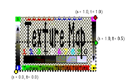
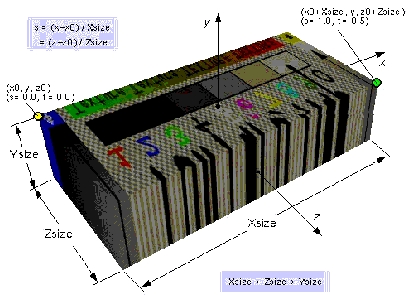
Means to describe urban worlds. Between the two geometric representations (i.e. face and primitives), preference has to be given to face description. The predefined primitives provide a simpler and more compact than face description. However, GIS models maintaining topology are based on boundary representations, i.e. they operate with faces, points, arcs, etc. (see Chapter 2). Moreover, most of the 3D models are reconstructed from surface measurements (see Chapter 7) that are difficult to combine with simple shapes (cone, sphere, cone). Another reason refers to the texturing of the geometry. VRML supports the two mechanisms to attach image (i.e. texture map, see Figure 4-1) to geometry, i.e. texture mapping and texture draping. The more precise adjustment, i.e. texture mapping, is permitted only for surfaces (composed of faces) or individual faces. The syntax is such that permits the usage of only one image file per VRML node, i.e. textures for a separate surface or an individual face have to be available in one image file. If, for example, one face has textures of different images for its two sides, then the face has to be described in two VRML nodes. However, there is no way to map, for example, six different images onto the six sides of a predefined shape cube. The operation in this case is texture draping, i.e. the image covers the entire shape according to a rule (see Figure 4-2). Thus, an accurate texturing of the images requires face description of real objects. Texture draping may be quite an appropriate technique for large surfaces represented by a set of faces, e.g. terrain (see Chapter 7). The geo-referencing between each polygon (i.e. triangle from TIN) and the corresponding piece of image (required for texture mapping) is not efficient: 1) requiring algorithms to generate image co-ordinates and 2) almost doubling the size of the VRML world.
The use of faces to describe urban objects inevitably leads to a need to group/separate objects, which can easily be achieved by Group and Transform nodes. For example, the building in Figure 4-3 is a group of three objects (main body, second body and third body) as each of them is a group of roofs and walls objects. Since the roof and the walls are represented by faces, they can be textured with separate image files.
Often, real objects used to be represented as lines and points in the GIS model. Although VRML support descriptions of lines and points, utilisation of predefined primitives is recommended. For example, lines and points can be displayed as tiny cylinders and little spheres. The substitution usually increases the readability of the VRML world. The VRML standard lines and points frequently cause "disappearing" of the object while navigating through the model. The effect is observed when the line object lays exactly on a face.
Means to describe large worlds. The Inline node offers a solution to the organisation of large data, typical of urban areas and often denoted as an obstacle to visualisation. The idea is that a very large VRML world can be parsed into several small worlds, which can be hosted separately (even on different servers). The Inline node maintains the reference to the worlds and their relative position to each other that allows the VR browser to assemble them into one. The node is quite popular for introducing predefined VRML models in virtual worlds. For example, models of a desk, a telephone, a fax machine, which are organised as individual VRML documents, can be located at different places in a room. Some models with quite complex geometry, sensors and scripts are already available on the Web for free utilisation and distribution (see Reitemeyer 1999). From the GIS aspect, the node may be successfully used for symbolising real objects such as trees, cars, planes, etc (see Chapter 8).
The LOD node permits LOD techniques (see Chapter 2) to be applied during visualisation in a simple and flexible manner. The syntax of the node requires the different representations and the switching parameter. The different geometric descriptions can be organised per object (or group of object) and organised in one or several VRML worlds. In practice, each object can have several representations in separate VRML worlds. Since each LOD is a regular VRML document, the construction of the LOD becomes entirely the designers wish. LOD might be created either for geometry or texture or both. For example, frequently used LOD for buildings are: very detailed, e.g. all geometric details of the buildings plus texture; less detailed, e.g. only geometry without texture; and coarse, e.g. only outlines of the buildings. VRML specifications agreed one parameter, i.e. the distance between the object and the viewer, to switch between LOD. The VRML worlds created so far usually have predefined LOD organised in separate VRML documents (Schickler 1997).
a) correctly rendered concave face |
b) incorrectly rendered concave face |
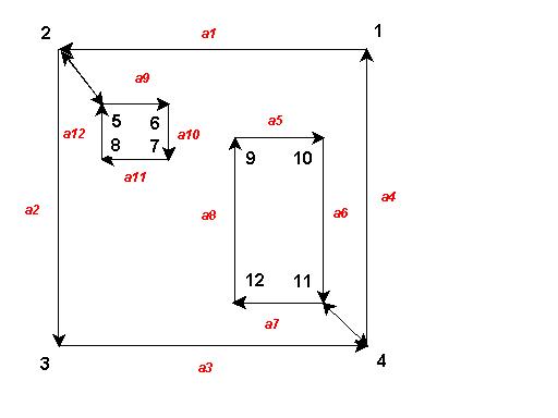
Another problem arises in the visualisation of holes. Based on the properties of 2 manifolds, the rendering engines need "opening" of the holes, i.e. connecting to the bordering face. Not all the VR browsers can handle holes, but the capable ones require opening. The operation can be achieved by a special ordering of the vertices. For example, the face in Figure 4-5, which has two holes, must have the following sequence of vertices: 1,2,5,6,7,8,2,3,4,11,12,9,10,11,1. The special order combined with a flag for concave face will enable a correct visualisation. A similar problem arises in the visualisation of overlapping or hosted faces. For example, one of the holes on Figure 4-5 may be a window, which has to be associated with a different colour. Similarly, to the visualisation of concave faces, an appropriate partitioning of the faces can ensure the correct visualisation.
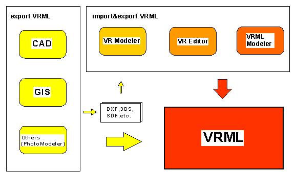
Software to generate a VRML world in its complete functionality is still to come. Since the birth of VRML, many vendors have already extended their file format to create VRML; others have started development of the software, based only on the VRML world format. To date, several types of computer programs can be used to create VRML worlds (see Figure 4-6). While the first group of software only exports, the second group exports and imports VRML worlds. The VRML worlds created by CAD and GIS are only scenes for visualisation, lacking the dynamics and possibilities for interaction. The second group comprises various software, which can be divided into three groups, i.e. VR modellers, VRML editors and VRML modellers. VR modellers (Medit, Pioneer Pro) provide extended tools for the design of illumination, shading models and texture mapping, viewing points, and camera positions, and they create richer VRML worlds than the first group. Most of them provide plenty of texture and shape libraries with means to map textures, modify and deform objects, create animation, etc., which allows fast and efficient design of 3D models. Unfortunately, the VRML nodes introducing dynamics (interpolators,sensors, routes) are not usually supported. VRML editors are extended text editors to manually type the body of the VRML world. Similarly to some HTML editors of the same range, they facilitate the user by furnishing the syntax of the standard VRML nodes. Although they support all the nodes, the method is not efficient because of the rather long time to create a single VRML world.
Perhaps, the most convenient way of designing VRML worlds is provided by VRML modellers, e.g. V-Realm, VR creator, Cosmo Worlds. This software operates directly on the VRML nodes, i.e. the user is able to modify the fields of the nodes. The GUI supplies windows for both graphics and text representations of the VRML world, as the individual solutions vary.
As can be realised, software to create VRML worlds exists in many variations. The extended GUI is the apparent benefit of their utilisation for display, interaction and modification of VRML worlds. Unfortunately, they are hardly appropriate for our goals. First, most of the modellers are stand-alone solutions and none of them is designed for access over the Web. Second, they do not have a connection to a database, i.e. the product of the modelling is a graphics file. Third, the maintained topology (in the modellers and VRML) is based on a 2-manifold subdivision (see Chapter 2) that requires a 3D topology creation after each change in the VRML world. An eventual utilisation of such software would require the development of a number of extensions: 1) translators from and to the GIS model, and 2) remote access to databases. Moreover, each user accessing the system must have installed the modeller and the extensions on his/her computer, which will effect the overall price of the system.
Figure 4-6: Software to create VRML documents
4.2 System architecture for a Web 3D GIS
The number of client/server architectures utilising VRML is still very limited (Coors and Jung 1998, Dodge et al 1998, GIS technology 1999, IGG 1999, Lindenbeck and Ulmer 1998, Zlatanova and Tempfli 1998). Some of the drawbacks of VRML and VR browsers listed above, the intensive improvement of the VRML specifications (three versions in four years) and the prevalent usage of VR techniques for entertainment (e.g. computer games) are some of the factors influencing the client/server realisations based on VRML.
Lindenbeck and Ulmer 1998 present a server application of VRML for geological surfaces and objects. The surfaces represented as triangular meshes are stored in related groups of files on the server. The VRML document is created on the fly, according to a prior selection of data (i.e. triangular meshes). The selection is formulated in an HTML form and processed by a CGI script. In fact, the options provided in the HTML form correspond to the names of the files that contain the meshes. The GCI script reads the geometry from the selected files and creates the VRML document. In this respect, the query completed is a query on server files rather then a spatial query. The role of the VRML document stops at simple visualisation i.e. complex geological structures are displayed in different combinations to facilitate the visual investigation of surface intersections.
The systems presented by Dodge et al 1998 and GIS technologies 1999 make connections to 2D GIS (ESRI) and visualise some information in dynamically created VRML documents. The utilisation of VRML is primarily for 3D visualisation. Since the third dimension is created by extrusion of a parameter (geometric or thematic) of the 2D database, the 3D models lack of vertical details. More elaborated use of VRML is intended in the research of the IGG, Rostock 1998. VRML documents are employed to query thematic attributes (e.g. eaves and ridge height, usage of floors) of objects.
Coors and Jung 1998 report the results of a prototype system (GOOVI-3D) for the interactive query of spatial and semantic information, and the visualisation of the results. The approach, based on CORBA-ID and Java applets, establishes direct access to databases inside the VRML document. The information is stored in two databases for geometry and topology, and semantics as the ID of an object is the link between them. The server accesses at least one of the databases to complete the result of query. The communication between the server and the client is controlled by Java applets, i.e. the function of the VR browser is only the execution of the applet. In this respect, the system architecture is client-oriented (see Chapter 2). The SQL query, which is specified in a specially designed SQL node (defined in a proto node), is conducted by Java applets. The result of the query is a set of ID of objects. The ID set is compared with the ID of existing objects (named nodes) in the VRML document and those that are equal are modified, e.g. highlighted. For this purpose, a second node is constructed to associate a node from the VRML document with the ID of an object. To manage the link between object and VRML node, an extension of the transfer protocol is developed. The VRML document is delivered initially as a script, which controls the relation between ID of objects and VRML nodes. Thus the user can identify the objects, query them and visualise results. This approach seems very promising but still cannot be widely implemented because it requires the specialised Web protocol IIOP.
4.2.1 Query, visualisation, modification
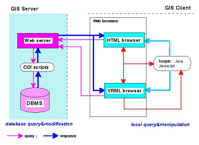
The system architecture used in our approach is a server-oriented, i.e. the CGI mechanism is utilised to access remote information. Among the approaches to access data on the Web (see Chapter 2), preference was given to the CGI scripting due to the well-experienced cross-platform mechanism, standard HTTP protocol, and availability of freeware API to access databases and create HTML fill-out forms. The proposed system architecture is intended for evaluating and verifying data organisation on the server and therefore less interest is paid to the functionality on the client site. The overall structure of the system comprises a Web browser with a VR plug-in on the client site and a Web server and a database system on the server site (see Figure 4-7). The system relies on HTML documents for the composition of queries and visualisation of data other than 3D graphics. Therefore a plug-in instead of a stand-alone VR browser is required. VRML documents are intended for identifying (selecting) objects to query and visualisation of spatial analysis. CGI scripts establish the protocol between the client and the server. They are responsible for the assembling of SQL queries, the access to the RDBMS and the creation of documents (HTML or VRML) on the fly with respect to the result of the query. Although in principle similar to the approach presented by Lindenbeck and Ulmer 1998, our system intends more sophisticated tasks for CGI scripts, HTML and VRML documents and thus goes a step further toward the analysis (spatial and semantic) of data.
The CGI mechanism with its specific client/server protocol subdivides the process of query, visualisation and modification of data into several different stages:
User identification and database selection. In the first stage, the user is given options from which to chose a model (e.g. each town or even neighbourhood might be in a separate database) and the range of interaction (query and visualisation, updating) has to be clarified. The database can be selected inside an initial HTML document (by filling in a form, pointing to an area of interest on a 2D raster map) or VRML document (pointing on a 3D map). The most convenient way is to provide each user with a number of default operations to query and visualise. Thus each user can send queries and receive responses (HTML or VRML documents) without restriction, except a change of data in the database.
Query. Recall Chapter 2, where a distinction between queries per object and complex queries is made. The request for information per object (a particular building, an owner or a list of co-ordinates of a parcel) can be organised in two steps: first, the object has to be identified, and second, the type of the information has to be specified. For example, the simple query "who is the owner of this building?" will require: 1) the means to point to the building and 2) an appropriate interface to specify the needed information. The first step can be formulated either in a VRML or an HTML document. In the HTML document, the query can be specified in a fill-out form (multiple choice or directly typing SQL queries). This means that the user has to be aware of the ID of the object in advance, which is often impossible. The alternative, i.e. pointing the object in the VRML document, is much more attractive. Despite the lack of a real pointing interface, combinations of sensors and scripts simulate the same operation (to be discussed in Section 4.2.2). The user visually chooses the object of interest as in a standard CAD system or GIS.
Both ways of identifying an object activate a CGI script on the server. The script delivers an initial HTML form, where the user makes further clarification and sends it back to the server. First, the form parameters are processed, the data needed according to the request are extracted, a document is created and then sent back to the client station. Since the CGI client/server architecture is stateless, each new query initiates the same process and results in a completely new document created on the fly. Very often, however, some information from already filled-in forms has to be forwarded to the next query. In this case, the information (some values of particular parameters) has to be memorised. Since the server has no memory of previous connections, parameters are kept on the client station. The intermediate document created contains the needed parameters in "hidden" for the user fields and passes them back to the server with the new query.
The two-step schema described above is appropriate only to query information (non-spatial and spatial) about a particular object. Many queries and much analysis cannot fit in the schema due to impossibility of clarifying objects in advance. Examples of such queries are "show the highest building in the town", "show all the administrative buildings", "show the common walls", " who are the owners of the buildings along this street?". The composition of such queries is rather too complex to be organised in VRML documents. Therefore special HTML fill-out forms, where the user types either the necessary SQL statement or other appropriate parameters, have to be created and hosted on the server. A detailed discussion is given in the next paragraph.
Data visualisation. The information delivered at the client site is displayed either in an HTML document (text, 2D graphics, etc.) or in a VRML document (3D graphics and text). For example, the query "show the way from the hotel to the nearest shop for shoes " will result in a subset of objects (streets and surrounding houses) that can be displayed in a VRML document. Animation may even route the user from the hotel to the shop. The result of a more complex request "show the way from the hotel to the nearest shop for shoes and the prices of the shoes" will be separated into two steps. First, the VRML document with the geometry will be displayed. A second user action, e.g. click with the mouse on the shop, will take care of the creation of an HTML document delivering information about prices. This limitation is related to the CGI mechanism to create documents on the fly. The first line sent by the server is the MIME type of document (see Chapter 2). The creation of two documents on the fly is impossible.
Figure
4-7: Client-server architecture for a 3D GIS on the Web
Local query and manipulation means temporary changes in the data on the client station. The local query can be understood as the exploration of some properties that are described in the VRML or HTML document, but can be activated and/or visualised only by user action. For example, one may want to compare several architectural plans for the reconstruction of existing facades. The existing facade will be stored in the database and the user will operate with several new views of the facade available as a separate image files on the server (see Figure 8-8). Another typical example is the design of vegetation and the evaluation of its future development. Different types and sizes of trees can be prepared and send to the client and the user can compare and evaluate the effects in different views. The way to make such temporary designs of geometric information is provided by the VRML, i.e. the suite of sensors, interpolators, and embedded scripts. The interpolators and scripts run only on the subset of data at this particular moment at the client station and, consequently, do not influence the information on the server, nor other clients.
The resulting documents can be displayed on the client screen as one window with several frames, several new windows, or combinations of them. In the prototype, system preference is given to one Web window, split into two or three frames. Separate windows provide the user with more freedom to resize and adjust observed models; however, the control on displayed information is disturbed, which leads to chaos on the client desktop. Examples of proposed GUI to query and display results of analysis are given in Chapter 8.
4.2.2 Creation of VRML documents on the fly
The VRML document can be created as a simple document for only visualisation and navigation or as a complex point-and-click, dynamics, animation enabled document. In the first case only the functionality of the VR browser, i.e. fly-over, walk-through, examine, pan, zoom, can be utilised that is applicable for queries where no further information is necessary.
The second type of VRML documents extends almost unlimitedly the ability of both queries and interactions with the model. The information about any object in a town can be collected by a series of user actions routing to ECMAscripts, CGI scripts or Java applets. Thus the next action can be either a new query to the database (on the server) or a query of the already delivered VRML document (on the client station). For example, pointing to the object with the mouse (a ECMAscript, the same document), the user can get specific information about the building, e.g. the name of the institution using it. The first click on the building may provide a standard HTML form (a CGI script, a new HTML document) with optional menu (e.g. the year of construction, the name of the architect). The second click on the same building may visualise an HTML form (a CGI script, new HTML document in a new window) where an SQL statement can be formulated. A click on the send button (a CGI script, a new VRML document) may execute a spatial query (e.g. "show the neighbouring houses"), which will be visualised in a VRML document. Thus, one pointing and three following actions by the user (clicks with the mouse) allow query of semantic and spatial information about a building.
The same mechanism can be applied in a more sophisticated way to explore complex buildings, which provide a variety of information, e.g. hotels, libraries, shopping centres. For example, the first clicking on the door of a hotel (an ECMAscript, the same document) will allow the user to enter. The second click on the reception desk (CGI script, new HTML document in a new window) will show prices and available rooms. The third click in the VRML document on the button (Interpolators and routes, the same VRML document) of the lift will open the door. The fourth click on a board to move the lift (CGI script, new HTML document in a new window) will ask the number of the floor. The fifth click on the send button (CGI script, new VRML document) will display the corridor on the 4th floor, and so forth. In this example, four clicks of the mouse activate three CGI scripts (three new documents are dynamically created), one ECMAscript and some VRML interpolators. Although not directly related to the tasks of a municipal system, the example illustrates the potentiality of such techniques.
An interesting issue is the creation of such a complex VRML document. First, the VRML document must allow the identification of the object, e.g. the possibility to click with the mouse. It has been mentioned before that the VR browser is not a complete GUI, e.g. the point-and-click operation is not a responsibility of the browser. The browser reacts to user actions (other than navigation) only if they are initially and explicitly described in the VRML document. The identification can be organised in two steps. First, a particular sensor has to be attached to an object (e.g. building), which will allow the user click on that object. Second, a reference between the object and its ID in the database has to be supplied to the user. In terms of VRML semantics, such a link can be established by the definition of a new node (see Appendix 2). The proposed node is a modification of the standard Touchsensor and consists of 1) a new field where the ID of the object can be given and 2) ECMAscript, which references object ID to a corresponding text. The new sensor visualises the ID of the object when the mouse is over the object. The ID visualised in this way facilitates the user in completion of the query. The actual identification is done by a click with the mouse.
Composition and display of the response follow the pointing to the object. What does the user want to achieve by interacting with this object: text, graphics, image, spatial analysis, attribute information? In our approach, the CGI script takes the decision as to which sensor is to be attached what object and what the resulting event has to be. The decision is taken during the dynamic creation of the documents. In general, the resulting event can be either fetching an individual file stored on the server or activation of VRML nodes: execution of CGI scripts, Java, ECMAscripts, Interpolators. Java and ECMAscripts have to be specified in a script node in the VRML document. Hence, the script nodes have to be embedded in the body of the VRML document on the fly as well. Clearly, the functionality of the system, and more particularly the GUI, rely on the CGI scripts. Thus CGI scripts become a critical component in the system and require careful organisation. Some of the problems that may occur are listed below:
An elegant way to avoid or reduce the effect of these drawbacks is by storing additional information in the database, which can help the script to compose the VRML document. To help in the description of the event-response process, information about the behaviour of objects is introduced. A variety of parameters, scripts, small VRML documents, animation, etc. per object that facilitate and simplify the work of CGI scripting can be captured in the database. Thus, a standardisation of CGI scripts can be implemented that will contribute to a reduction in their number and size. Long VRML documents can be partitioned into several smaller ones by recursive execution of the same script. In the example about the hotel and the lift, the board in the lift to move up will be a separate object with semantic and geometric characteristics and behaviour (move up). This behaviour can be described on a database level as "on-click activate which-floor CGI script" with two parameters event initiator (EI) and event response (ER). The number of parameters may vary depending on the type of interaction. The crashing-on-the-ground plane, for example, will need three parameters to identify the event (touch), the conflict object (ground) and resulting action (crash, e.g. short animation). Further elaboration on the issue will be given in Chapter 5.
4.3 Visualisation requirements
As discussed above, the VRML documents might contain a lot of data to represent geometry, shading, lighting, behaviour, etc. The important issue at this point becomes "supply" of appropriate data. The data needed for the VRML composition has different weights and can be separated into two groups: compulsory and extended data. The compulsory data, i.e. geometry, colours, texture and lights, are the minimum set of information for a simple VRML document to be visualised in the VR browser. The second group comprises the data important to establish links to other files and scripts or to enhance the GUI of the browser toward a complex interaction and a dynamic control over the scene. The software that designs the VRML documents (i.e. the CGI scripts) has to select parameters for both groups of VRML documents automatically. In this context, the existence of supplementary supporting information on the database becomes essential. Bearing in mind the syntax of VRML, established rendering principles and the dynamic status of VRML documents in the presented approach, the following visualisation requirements of the database can be drawn:
The new Web standard VRML has been presented and its suitability for urban modelling, analysis and visualisation of spatial analysis has been discussed. Several essential aspects of the discussion can be summarised, i.e. the language: 1) exhibits a potentiality that can be successfully utilised for visualising 3D data (sufficient realism, large amounts of data, complex shapes, lighting and viewing points can be easily organised), 2) supplies means to display spatial analysis, i.e. plenty of techniques to attract attention (animation, highlighting, pointing), 3) provides mechanisms to explore the models in real-time navigation mode, which eases the human perception and orientation; 4) allows access to a broad spectrum of HTML, VRML, multimedia documents on the Web, which facilitates urban management by enabling access to a variety of information. Moreover, the utilisation of VRML exploits the virtual reality techniques (walk-through, fly-over, explore) provided by the VR browser. Although VRML is not designed as a front-end engine for a Web GIS warehouse, extensions of the language, i.e. creating new nodes, Java, ECMAscript, CGI scripts, can fill up gaps and extend the interface. The conclusion that the language is appropriate for urban 3D modelling is drawn. Furthermore, the syntax of VRML requires the provision of specific information for the successful creation of the document, i.e. vertices, orientation of faces, colour, texture, descriptors for behaviour and dynamic, lights, views. Most of such data has to be available at the database level.
System client-server architecture proposes a solution for remote retrieval, query and analysis of semantic and spatial data on the Web. The approach employs the CGI mechanism to perform operations at a database level and embedded ECMAscripts at local (client) level. Such a system would require a lot of CGI scripts to control the complex process of urban planning unless a standardisation of the operations is implemented. The maintenance of additional information organised on the database is suggested, aiming at the improved organisation of CGI scripts. Thus, apart from the data needed for urban planning, the database has to maintain data supporting visualisation and interaction. Details about database organisation and structuring will be discussed in Chapter 5.
The GUI of the approach is based on complex VRML documents and HTML fill-out forms, which pursue the provision of sufficient means to query objects and complete spatial analysis. The suite of VRML and HTML documents is capable of either selecting predefined queries or composing new ones. The resulting dynamically created new VRML documents may be as complex as the starting one and, hence, used for further queries in two directions: to the server and to the local model on the client site. This is to say, our approach extends the role of the VRML from an end product for visualisation to GUI to identify objects, query their characteristics and spatial relationships. Supplementary SQL fill-out forms composed in HTML documents provide free standard access to all the information stored in the integrated database. The suite of SQL forms and VRML documents can act as a GUI to edit data and control changes on the server as well. Chapter 8 presents a number of GUI to perform a variety of operations on 3D GIS data.
The system architecture presented here allows fast development of low-cost applications. The client site has to be equipped with VR and Web browsers, which are available at very low prices or as freeware on the Web, i.e. the client sites do not cost time or money. Some investments are necessary but only for the visualisation of the server site. The server side requires Web server, DBMS and software for communication (i.e. CGI scripts). Again, low-price Web servers can be employed. Being the oldest method of accessing remote data CGI scripting is well supported and facilitated by various freeware libraries and APIs to access databases and create fill-out forms. A prototype system based on freeware components will be presented in Chapter 8.
VRML worlds:
Airport Schipol, Amsterdam, the Netherlands http://www.schiphol.nl/maps/3d.htm
Twente Music Centrum, Enschede, the Netherlands http://wwwseti.cs.utwente.nl/Parlevink/Projects/Muziekcentrum/codecompressed/vmc_zonderschisma.html
Grazer Congress Centrum, Graz, Austria http://www.gcongress.com
Alpine tour, Austria http://www.alpentour.at/index.html